Ethernet Simulation
Overview of Ethernet Simulation Engineering
As vehicle electronics evolve toward software-defined architectures and high-bandwidth communication, Ethernet-based ECUs increasingly handle large volumes of real-time data—such as sensor streams, over-the-air (OTA) updates, and ADAS information—posing significant challenges to network timing, security, and functional correctness.
To support robust ECU development, ETstudio can be used to build Ethernet simulation environments that emulate peer ECUs, switches, and traffic patterns. This enables early validation of:
- Communication behavior
- Protocol compliance
- System performance under realistic network loads
Ethernet simulation engineering requires close collaboration across requirements, software, testing, and validation teams. By simulating Ethernet nodes and traffic flows, developers can:
- Identify integration issues early
- Accelerate test cycles
- Ensure reliable deployment in complex automotive networks
Key Strategies
- Use OEM-provided Ethernet database files (e.g., XML or configuration sheets) to ensure signal and service accuracy
- Structure simulations with modular, reusable components for services like DDS
- Synchronize simulation models with hardware/software milestones
- Implement version control and documentation for simulation assets
Quick Start Guide
This section provides a step-by-step procedure to configure and execute basic Ethernet simulation tasks in ETstudio, including DDS and UDP traffic generation.
1. Hardware Channel Configuration
- Navigate to "Channel Assignment" in the main interface.
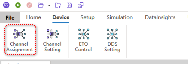
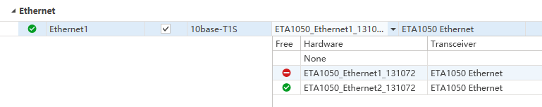
- Map the available physical communication channels to logical channels as required by the test setup.
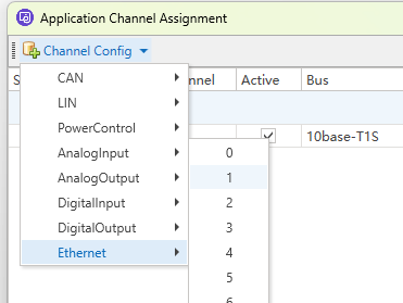
- Ensure the selected physical interface corresponds to the target Ethernet port on the test hardware.
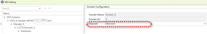
2. DDS Simulation Setup
- From the top menu, select Device → DDS Settings.
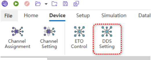
- Import the OEM-provided DDS configuration file (typically in XML format), which defines data types, topics, and Quality of Service (QoS) policies.

- Assign the configured logical channel to the appropriate DDS domain ID.
- Update the node configuration.
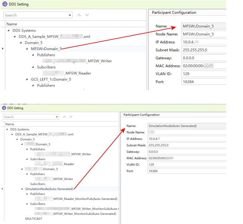
- Activate the simulation nodes to enable message transmission or reception according to the defined DDS model.
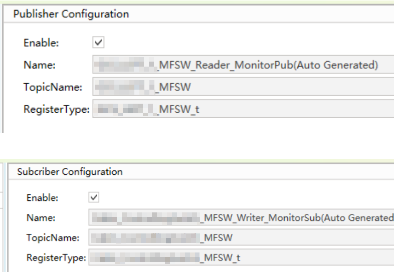
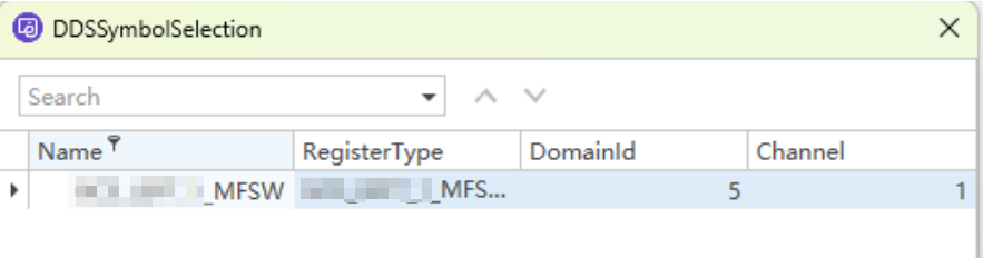
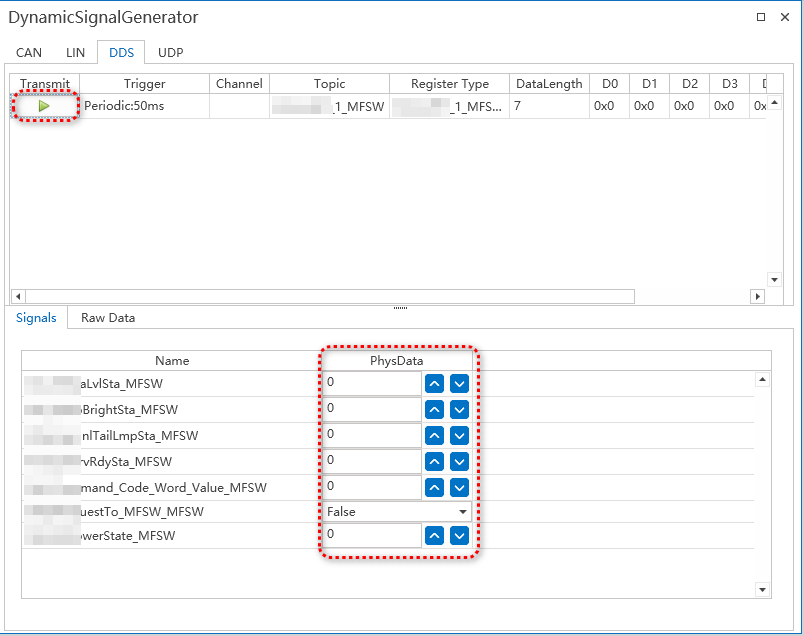
3. Transmitting DDS Frames
Once the DDS environment is initialized, simulated publishers will automatically transmit data samples on subscribed topics. Frame content, timing, and serialization are governed by the imported XML configuration. Real-time monitoring tools within ETstudio may be used to verify topic activity and data integrity.

4. Configuring and Sending UDP Frames
- Create a new UDP frame definition within the Ethernet simulation workspace.
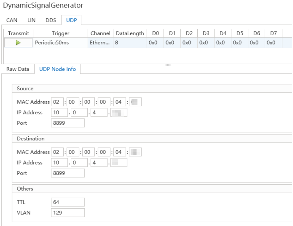
- Specify the destination IP address, port number, and payload format in the UDP node properties.
- Input the raw byte sequence or structured data to be transmitted.
- Apply the configuration and initiate transmission to simulate custom UDP-based communication (e.g., diagnostic protocols or proprietary telemetry).
Note: For mixed-protocol scenarios (e.g., DDS over UDP), ensure port and multicast group settings do not conflict between simulation components.