ETO
1. Introduce
1.1 What is the ETO System
The devices under test usually have a large number of I/O connections to actors and sensors. Modern flexible testing systems must stimulate the input and analyze the system response(i.e., the output) during functional testing. With the ETO system, we offers a compact, modular and scalable I/O test system. Due to its flexibility, the ETO system also supports complex measurement tasks. In addition, a high channel count can be configured in a compact setup.
1.2 Document Introduction
This document describes the ETO boards fuctions provided by the C Mini Program.
2. ETO7100
The ETO7100 is a 2-channel power output board, which can control the card output through three system variables.
2.1 ChannelEnable
Description
- ChannelEnable is the output voltage enable(0 - off,1 - enable)
Usage
  ETO::ETO7100_1_Ch1_ChannelEnable = 1;//Enable Channel 1 power supply
  ETO::ETO7100_1_Ch2_ChannelEnable = 1;//Enable Channel 2 power supply
2.2 CurrentLimitValue
Description
- CurrentLimitValue is the limit current value, ranging from 0 - 6350 mA
Usage
  ETO::ETO7100_1_Ch1_CurrentLimitValue = 6350;//Set the limit current value of Channel 1 to 6350 mA
  ETO::ETO7100_1_Ch2_CurrentLimitValue = 6350;//Set the limit current value of Channel 2 to 6350 mA
2.3 PowerVoltageValue
Description
- PowerVoltageValue is the output voltage value, ranging from 800 - 21276 mV
Usage
  ETO::ETO7100_1_Ch1_PowerVoltageValue = 18000;//Set the output voltage of Channel 1 to 18000 mV
  ETO::ETO7100_1_Ch2_PowerVoltageValue = 16000;//Set the output voltage of Channel 2 to 16000 mV
2.4 Voltage
Note: This system variable is only used to receive the PowerVoltageValue and dispaly it on the Diagram. If you want to monitor the voltage value, you need to check this system variable in the ETO System Configuration.
Description
- Voltage is used to receive the voltage value.
Usage
  ETO::ETO7100_1_Ch1_Voltage//Only receive ETO::ETO7100_1_Ch1_PowerVoltageValue
  ETO::ETO7100_1_Ch2_Voltage//Only receive ETO::ETO7100_1_Ch2_PowerVoltageValue
3. ETO7801
The ETO7801 is a 1-channel resistor board that can set the resistance value through a system variable.
3.1 ResistanceValue
Description
- ResistanceValue is the resistance value control, the range is 0.3Ω - 1MΩ, and the unit is 0.1Ω
Usage
ETO::ETO7801_1_Ch1_ResistanceValue = 10000;//Set the resistance value of Channel 1 to 1000Ω
3.2 Resistor
Note: This system variable is only used to receive the ResistanceValue and dispaly it on the Diagram. If you want to monitor the resistance value, you need to check this system variable in the ETO System Configuration.
Description
- Resistor is used to receive the resistance value.
Usage
  ETO::ETO7801_1_Ch1_Resistor//Only receive ETO::ETO7801_1_Ch1_ResistanceValue
  ETO::ETO7801_1_Ch2_Resistor//Only receive ETO::ETO7801_1_Ch2_ResistanceValue
4. ETO7610
The eto7610 is a 10-channel IO output board with channel switches set by a system variable for each channel.
4.1 ioValue
Description
- ioValue is channel control(0 - low,1 - high)
Usage
  ETO::ETO7610_1_Ch1_ioValue = 1;//Set Channel 1 to high level
  ETO::ETO7610_1_Ch2_ioValue = 1;//Set Channel 2 to high level
  ETO::ETO7610_1_Ch3_ioValue = 1;//Set Channel 3 to high level
  ETO::ETO7610_1_Ch4_ioValue = 1;//Set Channel 4 to high level
  ETO::ETO7610_1_Ch5_ioValue = 1;//Set Channel 5 to high level
  ETO::ETO7610_1_Ch6_ioValue = 1;//Set Channel 6 to high level
  ETO::ETO7610_1_Ch7_ioValue = 1;//Set Channel 7 to high level
  ETO::ETO7610_1_Ch8_ioValue = 1;//Set Channel 8 to high level
  ETO::ETO7610_1_Ch9_ioValue = 1;//Set Channel 9 to high level
  ETO::ETO7610_1_Ch10_ioValue = 1;//Set Channel 10 to high level
4.2 outputIOValue
Note: This system variable is only used to receive the ioValue and dispaly it on the Diagram. If you want to monitor the ioValue, you need to check this system variable in the ETO System Configuration.
Description
- outputIOValue is used to receive the ioValue.
Usage
  ETO::ETO7610_1_Ch1_outputIOValue//Only receive ETO::ETO7610_1_Ch1_ioValue
  ETO::ETO7610_1_Ch2_outputIOValue//Only receive ETO::ETO7610_1_Ch2_ioValue
  ETO::ETO7610_1_Ch3_outputIOValue//Only receive ETO::ETO7610_1_Ch3_ioValue
  ETO::ETO7610_1_Ch4_outputIOValue//Only receive ETO::ETO7610_1_Ch4_ioValue
  ETO::ETO7610_1_Ch5_outputIOValue//Only receive ETO::ETO7610_1_Ch5_ioValue
  ETO::ETO7610_1_Ch6_outputIOValue//Only receive ETO::ETO7610_1_Ch6_ioValue
  ETO::ETO7610_1_Ch7_outputIOValue//Only receive ETO::ETO7610_1_Ch7_ioValue
  ETO::ETO7610_1_Ch8_outputIOValue//Only receive ETO::ETO7610_1_Ch8_ioValue
  ETO::ETO7610_1_Ch9_outputIOValue//Only receive ETO::ETO7610_1_Ch9_ioValue
  ETO::ETO7610_1_Ch10_outputIOValue//Only receive ETO::ETO7610_1_Ch10_ioValue
5. Procedure
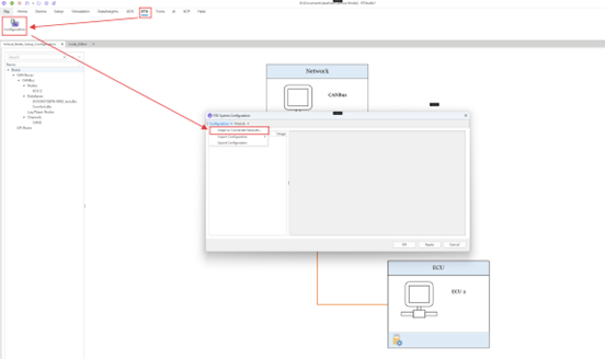
Users can find the connected board via ETO->Configuration->Adapt to Connected Modules in the main ETStudio interface.
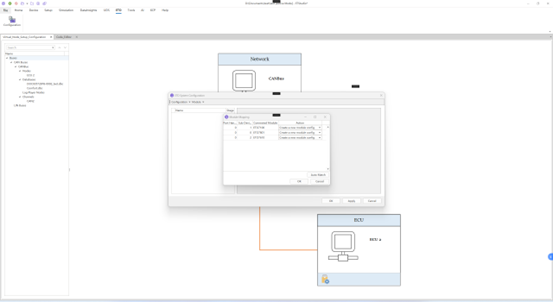
In the Module Mapping interface, the Port Handle represents the number of the same board, and if there are two eto7100 boards, its Port Handle is 1. Sub Device Number displays the number of different boards. Then click OK.
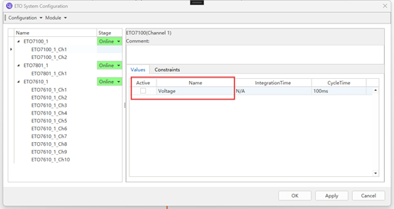
In the following picture, you can check the return value(Voltage Resistor outputIOValue) under the corresponding board channel, and after setting the board in the mini program, you can view the image of the corresponding system variable in Home->Diagram. Then click OK.
Double-click the ECU to enter the mini program editing interface and edit the board settings in the mini program.
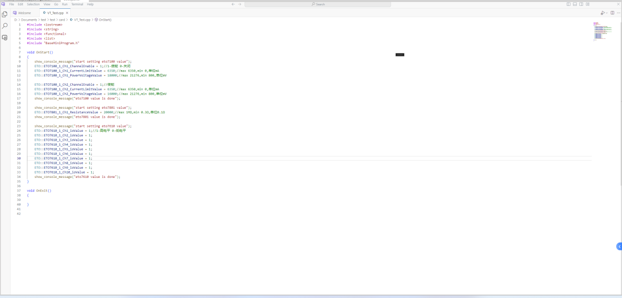
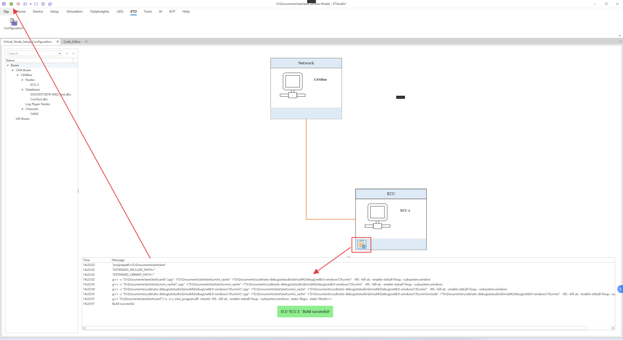
Then you can compile the mini program to see if the program is correct and click the start button in the upper left corner.
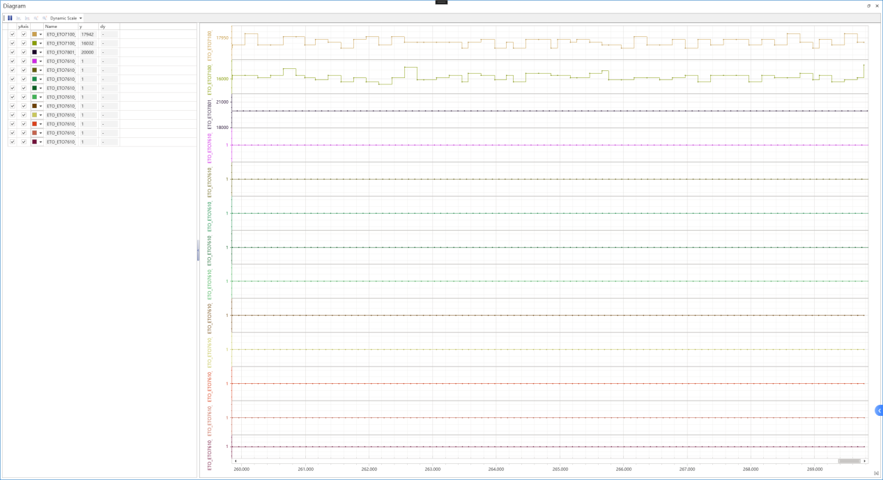
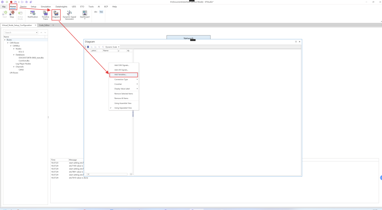
Click Home -> Diagram and right-click on the blank space on the left side of the Diagram to select Add Variables.
You can view the corresponding system variable image in the ETO namespace under the Global Variables Selection that appears.
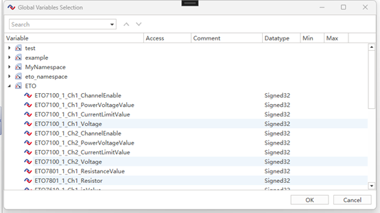
An example of the image shown is below: