Simulation Setup
The Simulation Setup in ETStudio is a graphical environment for designing and managing virtual networks. It allows users to model bus systems by adding and configuring simulated ECUs (Electronic Control Units), defining their interactions, and integrating test scripts. This setup is foundational for validating communication protocols (e.g., CAN, LIN) in a hardware-free environment, enabling efficient development and testing of embedded systems.
Simulation Configuration Tree
The Simulation Configuration Tree (or Network Hierarchy) in ETStudio's Simulation Setup is a structured panel that organizes and controls all elements of a simulated network. Located on the left side of the interface, it provides a hierarchical view for configuring bus systems, enabling users to:
On this interface, you can configure CAN or LIN networks. Under the configured network nodes, you may:
-
Import and manage description files (e.g., DBC for CAN networks or LDF for LIN networks)
-
Insert online replay blocks (.blf/.asc) to replay recorded bus traffic.
-
Assign communication channels (CAN, LIN) to hardware interfaces.
-
Configure virtual ECUs (Network Nodes) with C mini programs.
-
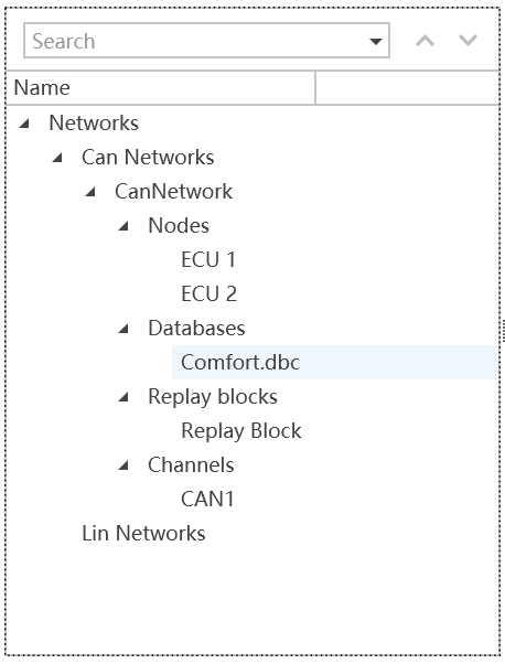
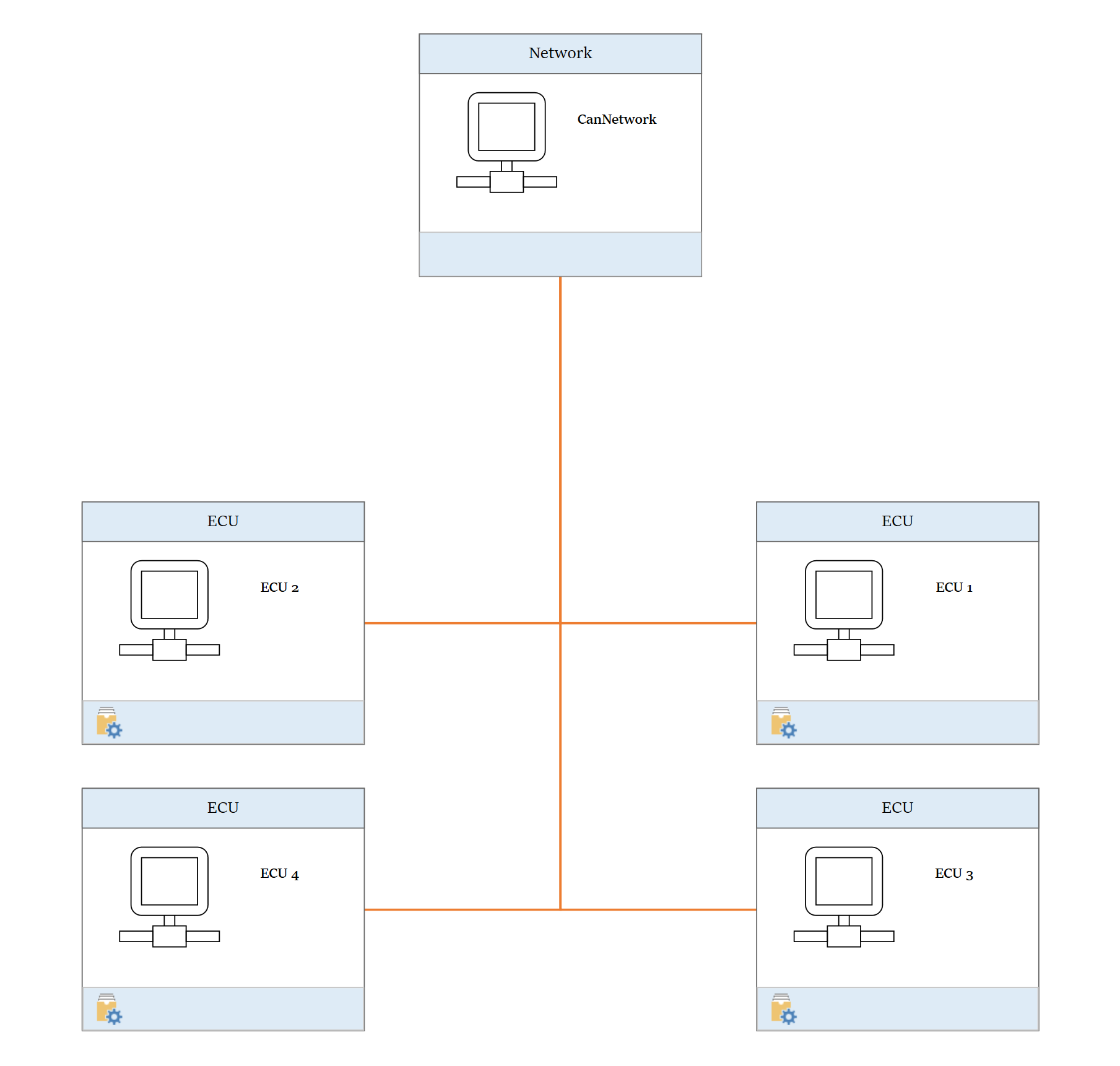
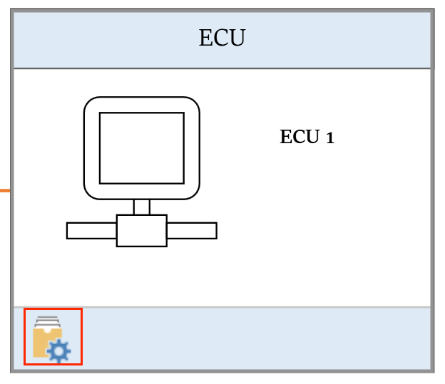
Network Nodes
A Network Node in ETStudio's Simulation Setup is a virtual representation of an ECU (Electronic Control Unit) or device within a simulated bus network. It mimics real-world behavior such as message transmission/reception, signal processing, and interaction with other nodes. Users can configure its properties and attach C mini programs to define its logic. Network Nodes are essential for testing and validating bus systems before hardware deployment, supporting protocols like CAN, LIN.
Supported Node Types
- Network
- ECU Node
Node Operations Guide
- Adding a ECU Node
- In the Simulation Configuration Tree, right-click on Nodes
- Select Insert Network Node to create a new ECU
- Attaching/Editing C Mini Programs
- For new ECU Nodes:
- Double-click the node to attach a C mini program
- For existing ECU Nodes:
- Double-click the node to edit the current program
Note: Currently only single C mini program files are supported per node. Future updates will include folder support.
- Viewing Node Information
- Hover over any ECU Node to display:
- Node type (Network/ECU)
- Node name
- Associated C mini program path
- Modifying Node Configuration
- Right-click the ECU node and select Configuration
- Adjustable settings:
- Name (e.g., rename
ECU_1toECU_Node_1) - Comment
- Associated program path
- Name (e.g., rename
Note: Node changes during measurement require restarting the measurement to take effect.
- Compiling the Node
- Click the Compile button to build the attached program
Note: All programs must be compiled before starting measurement.
- Running the Simulation
- Click the Start Measurement button in the main window
- Executes all nodes' programs simultaneously