Diagnostic Module Configuration
ETStudio's Diagnostic Module provides a powerful diagnostic console that enables users to fully customize transmission (Tx) and response (Rx) requests for vehicle communication. This guide details the configuration of Transport Layer, Service Layer, and Security Access (Seed & Key) parameters to ensure optimal diagnostic performance.
Transport Layer Configuration
The explanations for each parameter are as follows:
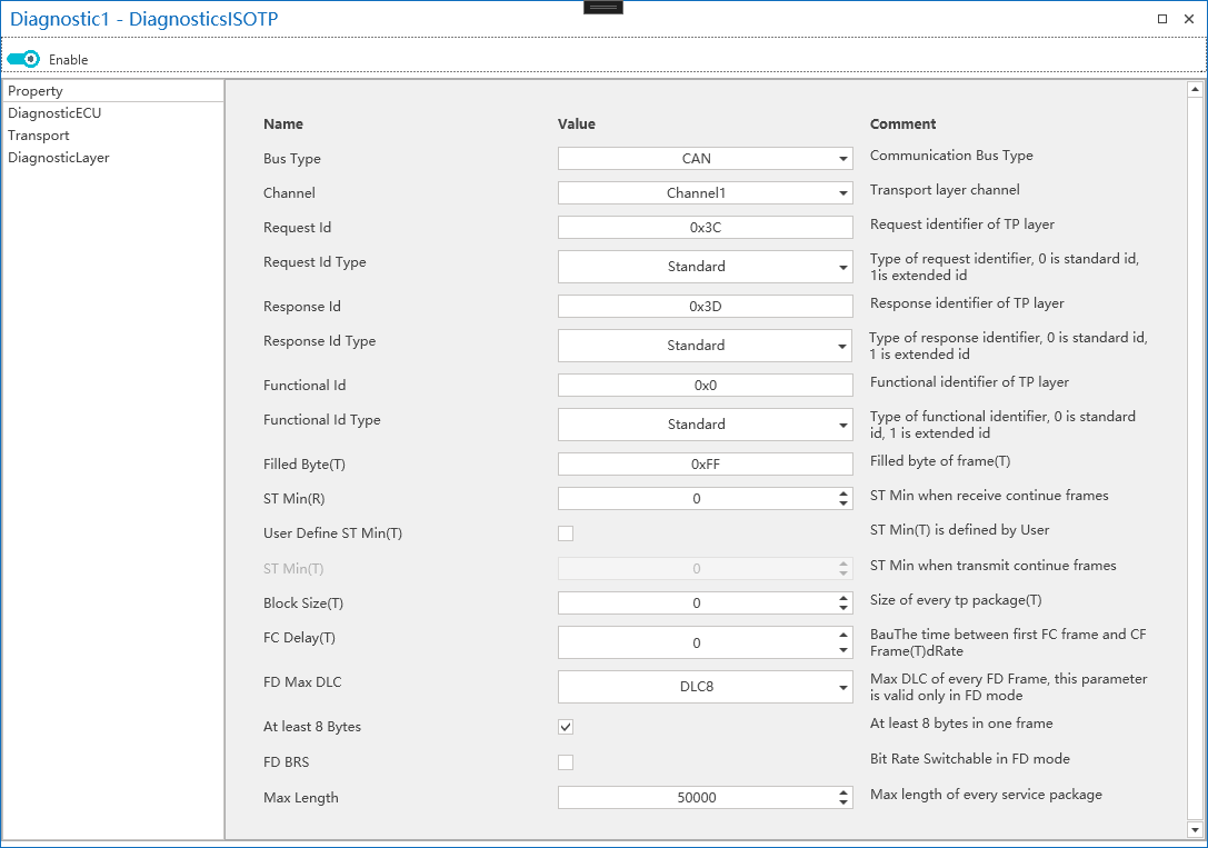
- Bus Type: diagnostic transport layer type, currently, CAN/CANFD is supported. User can choose from a drop-down list, as shown in the figure below:

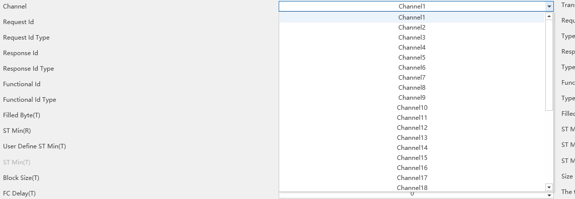
- Channel: the logical channels used by the diagnostic module. And here it is used to select which logical channel of the system the current diagnostic module will use. Selection is made through a drop-down list, as shown in the figure below:
-
Setting the ID for diagnostic request, response, and functional frames of the diagnostic module PC tool end.
-
Request Id Type/Response Id Type /Function Id Type: Setting the ID type for the diagnostic request, response, and functional frames on the PC tool end of the diagnostic module, whether it is a standard frame (11 bits) or an extended frame (29 bits), as shown in the figure below:

-
Filled Byte: during the transmission process, when the actual effective bytes are less than a CAN message data frame, the remaining data segment is filled with padding bytes. For example, if a CAN message frame is 8 bytes long and the effective transmission bytes are 【0x02, 0x10, 0x02】, with the padding byte being 0xAA, then the actual message bytes are 【0x02, 0x10, 0x02, 0xAA, 0xAA, 0xAA, 0xAA, 0xAA】.
-
ST Min: shortest reception time interval. When ETStudio's diagnostic module acts as the receiving end, it supports the shortest time interval between diagnostic frames when receiving continuous frame messages. This parameter is the response to the diagnostic client. Setting it to 0 indicates support for receiving at the shortest possible time interval.
-
Block Size: The size of the received Block. When ETStudio's diagnostic module, acting as the receiving end, receives continuous frame messages, it indicates the size of the data block that can be received at one time. This parameter is provided as a response to the diagnostic client. Setting it to 0 means that it can receive a data block of any size at once.
-
FD Max DLC: when the transport layer is set to CAN FD, the maximum number of bytes that can be transmitted in a single frame is 64 bytes (DLC=15), but this parameter is adjustable, with the adjustment range as shown below:

- Max Length: This parameter is meaningless for standard CAN/LIN. During multi-frame transmission, when the DLC length is 8 bytes, the first frame uses the low four bits of the 0th byte
- the 8 bits of the first byte, totaling 12 bits to represent the size of the packet for a single transmission, which is up to 4095 bytes, as shown in the figure below:
Service Layer Configuration
Controls diagnostic session timing and ECU response behavior.
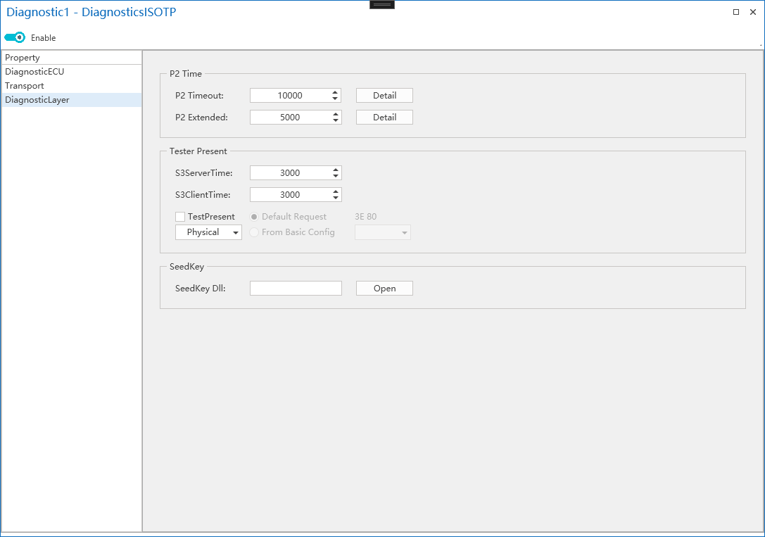
S3 Server Time: Timeout before ECU reverts to Default Session.
S3 Client Time: Interval for sending TesterPresent (0x3E) to keep a session active.
The schematic diagram for the two parameters mentioned above can be viewed by clicking the Detail button.
P2 Timeout: it indicates the shortest time interval after which the ECU must reply to a diagnostic request frame. For the diagnostic tool end, this parameter can be used as a timeout judgment parameter after sending a request. For example, if the diagnostic tool sends a diagnostic message and does not receive a reply within the P2Timeout period, it is considered that the request has failed and the process exits due to a timeout.
P2 Extended: when the diagnostic tool sends out a diagnostic message, if the ECU being tested does not have enough time to respond within the P2 Timeout period, it replies with a 7F XX 78 message, informing the diagnostic tool that it is unable to respond in time and that it needs to wait longer before replying. After the ECU sends the delay waiting message, the waiting time parameter is switched to P2Extended. The diagnostic tool's timeout judgment parameter needs to switch to P2Extended after receiving the delay waiting message.
Seed&Key
Load External Seed&Key DLL
During the diagnostic process, issues related to secure access, known as Seed & Key, are encountered. The ETStudio diagnostic module supports the loading of Seed & Key algorithms through a DLL, which is compatible with the calculation interface of mainstream tools.